A while ago (years) I bought a couple of 'corncob' light bulbs like this:
- one cool white and one warm white. COB hadn't arrived yet so the LEDs were all discrete components; 6 boards with 16 LEDs each plus another 8 on the end, total 104. The WW one wasn't very bright but apart from that they were OK.
Until, that is, the CW one began to flicker, then 52 of the LEDs went off - half of the end ones and three of the 6 boards. I stuck it on one side rather than throw it out, because there are a lot of LEDs which might be useful for something. Recently I dug it out and thought I might investigate the fault.
The end cap just pulled off - not glued, just located by pins - and I found that the cap was just holding everything in place. The end board came out followed by each of the six 16-LED boards, and finally a small PCB with power components. The power board was wired to the bayonet cap connector (240V AC) and delivered about 176V DC to the end board and one long board. It was arranged so that the DC was split two ways at the end pcb, each feeding four LEDs and then wired across to a side pcb. Three side pcbs were wired in series and the common return was on the last one. This gives two parallel strings of 52 LEDs wired in series, each fed by the 176V DC.
The whole of one string was off, so the fault was obviously either an open LED or a bad connection. I checked the voltage down the chain from the top until it went from 115V at one LED to almost zero at the next - obviously this was the bad LED. Using the diode test function on my DVM, I tested the LED and it was open both ways. But so was the next. and so was every other one on both strings. It seems that the junction voltage on these LEDs is more than the 2.8V which the meter uses for testing. Checks on other diodes proved that the meter was working fine.
I went around every connection in the lamp, reverting to my experience as a quality control engineer. I found that about 10 connections had already been reworked and a further two were dry - clearly the quality of soldering is questionable. Perhaps if the labour costs are cheap enough, it makes it financially viable to employ remedial QC workers even though the product is bad. After all, it only needs to work long enough to get into the end user's appliance for a few minutes. After my loving ministrations, the lamp was still faulty so I decided that the dead LED was probably the only remaining fault.
I didn't have any spare diodes of this type, so I had to improvise. With 176V across 52 diodes, that's only 3.4V each, so the extra voltage across each of the others when one is bridged is only 66mV or about 2%. Of course the higher voltage means more power dissipated in each one, so shortens the lifespan, but not significantly. Luckily they fail open-circuit; if they failed short-circuit there would be a runaway chain effect, hardly noticeably at first but culminating in total extinction and a bang. I could replace the LED with a suitable resistor or diode but that meant more calculations and anyway, I don't have many resistors in stock.
Having decided that it was worth a try, I just put a short circuit across the faulty one and switched on.
The string was still dead! And now the 115V dropped at the next LED. I was wondering if I was actually causing a runaway effect. But in fact, all it was was that both diodes had died together. I won't keep doing this of course, but I shorted out the second diode too, and everything worked again. It all went back together without problems (or glue) and I now have a fully working bulb again.
All this is a lot of trouble to go to for one light bulb, but I was curious about the construction and the fault. More recently, the advent of chip-on-board (COB) LEDs has improved the performance of LED lighting, although I don't suppose the build quality is necessarily any better. The lesson is probably the old one - that cheap products with no warranty are likely to be a bad investment in the long run. I've had many LED bulbs since this one (in fact, it's hard to find anything else these days) and so far they have been very satisfactory. Nowadays I can buy an LED bulb for little more than the incandescent ones used to cost, so it makes sense to buy from a well-known manufacturer. They have their brand reputation to protect.
The trials and errors of an unrepentant follower of lost causes in the world of non-functional human technology.
Friday, 5 October 2018
Wednesday, 18 May 2016
Not Quite Toast [Dell laptop]
OK, here's a fine tale. Believe it or not - this story, and the accompanying photos, are absolutely true and unaltered.
In another life, I was an I.T. Support engineer in an academic institution. Although it wasn't strictly part of the job, I would often undertake minor repairs to the staff kit, such as mending frayed power cables or fixing broken connectors. There are quite a few tales there too, but I digress.
One day, a staff member came into the Helpdesk office bearing a carrier bag and a very sheepish expression. He had, he said, had an accident with his laptop, and it wasn't working, and did I think I could fix it? He opened the bag to reveal this mess:
After I stopped laughing (cruel, I know) I had to inform him that there was a chance that it might be beyond even my legendary abilities to resurrect this unfortunate item, and that he should bid a sorrowful farewell to his files and seek laptops new. This suggestion was accepted with a degree of rueful acknowledgement that in truth, he hadn't held out much hope anyway.
The full sequence of events was related. He had needed to go out of the house for a short time, and being conscious of the possibility of burglary he had looked around for a suitable place to conceal the laptop in his absence. As he was in the kitchen, the oven seemed to be a place that any thief would never look for a laptop, so in it went. Shortly after that, his wife came into the kitchen and proceeded to prepare the dinner, consisting in part of a nice apple crumble (you can see where this is heading). I suppose a black laptop does look a bit like a baking tray, but anyway for whatever reason she didn't realise the situation and switched on the oven to heat up while she mixed. After a while she noticed a distinctly un-crumbly smell and opened the oven....
Credit where it's due. Although the oven temperature clearly exceeded the melting point of most of the plastic components and turned them into a Dali-esque sculpture, this Dell has an alloy frame and top and bottom covers - these were surprisingly unaffected but the rest was, well, toast. The screen had melted and all the keys had evaporated from the keyboard, and everything was in a sorry state. I took the above photos just for the record because it's a sight you don't see often (although with Lithium Ion batteries becoming ubiquitous in cheap kit and charging not always sensibly controlled, we may see more incendiary incidents).
My colleague having gone off to throw himself under a handy train, I put the remains on a shelf and got on with something else.
Some time later I was poking at the pile of ash and I began to wonder what would happen if I connected a power supply to it. "Nothing" was the most I expected, although "lots of smoke and sparks" was also a possibility. Anyway, I went ahead and with the fire extinguisher close at hand, I connected the power unit and switched on. To my utter amazement, this is what I saw...
Not only did it not spark or catch fire, it actually booted as far as the command line and (rather superfluously) informed me that it couldn't see the hard drive, it couldn't understand the power supply parameters and it might not feel like charging the battery. It told me to strike the F1 key to continue but as you can see, there no longer was any F1 key. In fact if the key switches had not melted, it may have got further, but in the event I thought that it had already gone far beyond the call of duty, so I switched off.
The upshot of all this was that I chiselled out the hard drive and found that it was still operational, and I was able to recover my colleague's data for him. He was overjoyed and promised to tell Dell how impressed he was with the durability of their product, and he took away the bag of ashes for a decent burial.
Actually, it was a bit sad. This sturdy little machine was nobly doing its job and didn't ask, or deserve, to be baked to a crisp. I thought it was an effort worthy of high commendation that, with its last breath, it mustered enough life energy to let us know that it wasn't quite beaten. If it had not managed that, I wouldn't have attempted to remove the hard drive and try recovering the data, and all my colleague's work would have been lost.
Rest in peace, little champion.
In another life, I was an I.T. Support engineer in an academic institution. Although it wasn't strictly part of the job, I would often undertake minor repairs to the staff kit, such as mending frayed power cables or fixing broken connectors. There are quite a few tales there too, but I digress.
One day, a staff member came into the Helpdesk office bearing a carrier bag and a very sheepish expression. He had, he said, had an accident with his laptop, and it wasn't working, and did I think I could fix it? He opened the bag to reveal this mess:
After I stopped laughing (cruel, I know) I had to inform him that there was a chance that it might be beyond even my legendary abilities to resurrect this unfortunate item, and that he should bid a sorrowful farewell to his files and seek laptops new. This suggestion was accepted with a degree of rueful acknowledgement that in truth, he hadn't held out much hope anyway.
The full sequence of events was related. He had needed to go out of the house for a short time, and being conscious of the possibility of burglary he had looked around for a suitable place to conceal the laptop in his absence. As he was in the kitchen, the oven seemed to be a place that any thief would never look for a laptop, so in it went. Shortly after that, his wife came into the kitchen and proceeded to prepare the dinner, consisting in part of a nice apple crumble (you can see where this is heading). I suppose a black laptop does look a bit like a baking tray, but anyway for whatever reason she didn't realise the situation and switched on the oven to heat up while she mixed. After a while she noticed a distinctly un-crumbly smell and opened the oven....
Credit where it's due. Although the oven temperature clearly exceeded the melting point of most of the plastic components and turned them into a Dali-esque sculpture, this Dell has an alloy frame and top and bottom covers - these were surprisingly unaffected but the rest was, well, toast. The screen had melted and all the keys had evaporated from the keyboard, and everything was in a sorry state. I took the above photos just for the record because it's a sight you don't see often (although with Lithium Ion batteries becoming ubiquitous in cheap kit and charging not always sensibly controlled, we may see more incendiary incidents).
My colleague having gone off to throw himself under a handy train, I put the remains on a shelf and got on with something else.
Some time later I was poking at the pile of ash and I began to wonder what would happen if I connected a power supply to it. "Nothing" was the most I expected, although "lots of smoke and sparks" was also a possibility. Anyway, I went ahead and with the fire extinguisher close at hand, I connected the power unit and switched on. To my utter amazement, this is what I saw...
| Phoenix or what? Way to go, Dell! |
The upshot of all this was that I chiselled out the hard drive and found that it was still operational, and I was able to recover my colleague's data for him. He was overjoyed and promised to tell Dell how impressed he was with the durability of their product, and he took away the bag of ashes for a decent burial.
Actually, it was a bit sad. This sturdy little machine was nobly doing its job and didn't ask, or deserve, to be baked to a crisp. I thought it was an effort worthy of high commendation that, with its last breath, it mustered enough life energy to let us know that it wasn't quite beaten. If it had not managed that, I wouldn't have attempted to remove the hard drive and try recovering the data, and all my colleague's work would have been lost.
Rest in peace, little champion.
Thursday, 5 May 2016
Who's bin naughty then? [Brabantia]
I always wanted one of those lovely Brabantia waste bins with the soft-touch latching lid. After trying the pedal, swing-top, lift-top, no-top and goodness knows how many other types, the idea of just touching the lid for it to open smoothly by itself and latching it shut with a gentle push-click was heaven. Also, they come in stainless steel and have a removable inner bin. They were always well out of my budget range, but I was lucky to find two at once - one 40 litre one for the kitchen, with a flat back to save space, and a smaller 35 litre cylindrical one for the bathroom, at a very reasonable price second-hand on eBay.
All went well for a few years. The main weakness with these is the peg onto which the spring latch grips, which can break if the lid is slammed carelessly. The mating spring catch is also consumable but is available as a spare part; on the early bins the peg is moulded in one piece with the whole lid frame, which is in turn hot-welded to the stainless steel outer. Thus, a broken peg means a new lid assembly which is a significant proportion of the cost of a new bin. These days I think that the peg is made separately and in any case there are third-party suppliers offering replacements in clip form, which will also fit the old style lid. However, as befits this mad household, my family were unwilling to break the bin in the conventional fashion. We waited until something was jammed over the peg and then tried to close the lid - when it wouldn't close, it was forced until it did, in the process twisting the lid and breaking the hinge at one end. The lid is supported by quite a strong spring acting on the hinge axis, The hinge can't be dismantled without removing the lid frame from the steel, which means breaking off all the moulded weld points and re-fixing the frame after repair with another method. So, I was faced with either buying a new lid assembly or repairing the existing hinge in situ against the spring pressure.
The form of the lid is like a plastic plate with the back edge rolled into a half-tube, inside which is the hinge pin (full-length axle joining both sides). The plastic had cracked so that the plate was separated from the remaining part of the half-tube attached to the spring.
Firstly I allowed the lid to open fully so that the spring was in its least stressed position. This allowed the two broken parts to be aligned and glued, but the joint was not nearly strong enough to cope with the spring force when the lid was being closed; so I clamped the joint in position and used epoxy glue (Araldite) both to join the pieces and to fix a short steel pin over the break at each end (along the edge of the plate/tube). Shortened panel pins were ideal for this, strengthening the joint without projecting on either side of the joint - if they did it would interfere with either the hinge action or the next phase of repair.
I looked for a length of steel or plastic pipe of the same diameter as the 'rolled half-tube' section. As it happened I had just replaced a shower curtain rail because the plastic coating had disintegrated; under it was a plain mild steel tube (a bit rusty) of 1" diameter. However, this was a little small for what I had in mind, which was to cut and shape a section to fit over the plastic rolled half-tube. When glued in place all along the length, it would sheath and essentially replace the function of the plastic half-tube and support the broken part completely. As it was all I could find, I cut the steel tube to length, de-rusted it and used emery paper to give it a brushed appearance like the bin surface, then cut it down its length in two places to give a part-cylinder. Then I needed to gradually open up the cylinder to a larger radius, until I could clip it firmly over the plastic tube. I then coated the whole inside of it with polyurethane glue (Gorilla Glue), wiped the plastic tube with water to speed the cure, and clipped it into place over the plastic tube. I clamped it in various places and left it overnight to cure, and when ready I tested the action with complete success.
The only remaining job was to give the bare brushed steel a coat of polyurethane laquer to protect it from the horrid bin contents, and to make it look like part of the original equipment.
![]() |
| The lid in question |
All went well for a few years. The main weakness with these is the peg onto which the spring latch grips, which can break if the lid is slammed carelessly. The mating spring catch is also consumable but is available as a spare part; on the early bins the peg is moulded in one piece with the whole lid frame, which is in turn hot-welded to the stainless steel outer. Thus, a broken peg means a new lid assembly which is a significant proportion of the cost of a new bin. These days I think that the peg is made separately and in any case there are third-party suppliers offering replacements in clip form, which will also fit the old style lid. However, as befits this mad household, my family were unwilling to break the bin in the conventional fashion. We waited until something was jammed over the peg and then tried to close the lid - when it wouldn't close, it was forced until it did, in the process twisting the lid and breaking the hinge at one end. The lid is supported by quite a strong spring acting on the hinge axis, The hinge can't be dismantled without removing the lid frame from the steel, which means breaking off all the moulded weld points and re-fixing the frame after repair with another method. So, I was faced with either buying a new lid assembly or repairing the existing hinge in situ against the spring pressure.
The form of the lid is like a plastic plate with the back edge rolled into a half-tube, inside which is the hinge pin (full-length axle joining both sides). The plastic had cracked so that the plate was separated from the remaining part of the half-tube attached to the spring.
Firstly I allowed the lid to open fully so that the spring was in its least stressed position. This allowed the two broken parts to be aligned and glued, but the joint was not nearly strong enough to cope with the spring force when the lid was being closed; so I clamped the joint in position and used epoxy glue (Araldite) both to join the pieces and to fix a short steel pin over the break at each end (along the edge of the plate/tube). Shortened panel pins were ideal for this, strengthening the joint without projecting on either side of the joint - if they did it would interfere with either the hinge action or the next phase of repair.
I looked for a length of steel or plastic pipe of the same diameter as the 'rolled half-tube' section. As it happened I had just replaced a shower curtain rail because the plastic coating had disintegrated; under it was a plain mild steel tube (a bit rusty) of 1" diameter. However, this was a little small for what I had in mind, which was to cut and shape a section to fit over the plastic rolled half-tube. When glued in place all along the length, it would sheath and essentially replace the function of the plastic half-tube and support the broken part completely. As it was all I could find, I cut the steel tube to length, de-rusted it and used emery paper to give it a brushed appearance like the bin surface, then cut it down its length in two places to give a part-cylinder. Then I needed to gradually open up the cylinder to a larger radius, until I could clip it firmly over the plastic tube. I then coated the whole inside of it with polyurethane glue (Gorilla Glue), wiped the plastic tube with water to speed the cure, and clipped it into place over the plastic tube. I clamped it in various places and left it overnight to cure, and when ready I tested the action with complete success.
The only remaining job was to give the bare brushed steel a coat of polyurethane laquer to protect it from the horrid bin contents, and to make it look like part of the original equipment.
![]() |
| It's bin mended! |
Wednesday, 4 May 2016
Return of the Were-Rabbit* [Dutch Dwarf Lop]
Rabbits are very cute, I suppose, although skinny - when I handle a rabbit it always reminds me of a velvet pouch full of bones - but they have ferociously efficient teeth. I haven't been fully bitten, only nipped, but having seen what they can do to thin aluminium sheet and copper wiring, I don't want to have those chisel teeth anywhere near my flesh.
My daughters have for years had two pet rabbits at any one time (in rotation - one of the first pair had to be replaced as too aggressive, another disappeared overnight probably to sustain some nocturnal predator, and two died) and they had occasionally been allowed in the house. She Who Must Be Obeyed likes the idea of "house rabbits". I let this happen assuming that at least the poop would be cleaned up - not always the case, unfortunately - but I stopped it after discovering that the new sofa was ripped and the Christmas lights and my computer power supply lead had both been sliced into several parts by rabbity dentition. The power was on at the time, yet the perpetrator was unharmed. Maybe their teeth are made of a ceramic non-conductor.
Anyway, after an interval long enough for me to forget the above incident, Bagel - one of the current pair - was found demonstrating rigor mortis one day. The pair were well bonded and it was clear that the survivor Thumper would pine after his departed friend during the night, and the weather was cold with no cosy partner to snuggle up to. So my elder daughter decided that she would take him into her bedroom overnight until either a new partner was found or he was re-homed. I thought little about this as she is now old enough to deal with things like animal care. Or so I thought.
After a couple of weeks, one day when I eventually surfaced from my bed I was informed that there had been a power cut for several hours. On investigating I discovered that the 'power cut' was restricted to our own house, and no-one had thought to check the fusebox. In fact, the main safety RCD had tripped and resetting it restored the power immediately. A few days later it happened again, this time taking out the RCD and the Miniature Circuit Breaker protecting the mains power outlets. Resetting both restored power again, and I checked every item connected to the mains circuit downstairs but could find no problem. The next time it occurred I found that on resetting the trips they immediately dropped out again (but intermittently) and I spent the next two hours carefully inspecting every outlet in the house and its associated loads.
The fault, when finally revealed, was horrifying. In my daughter's bedroom, she had a four-way power extension plugged into the wall outlet and had routed the cable under her desk, round the back of her high bunk bed and up to her bedside cupboard to supply lights and phone charger. She had created a curtained-off "den" under her bed into which she used to retreat to read in privacy, and she had lined the den with spare bedding and pillows and a bookcase. When I looked into the den I discovered that she had been using it as a rabbit hutch for Thumper , and she had not been cleaning up the rabbit poop and uneaten food. The bedding and carpet were soaked with urine. There were shredded books in evidence, and on lifting the bedding I found that the extension cable had been extensively stripped - all three wires were bared and had been sparking together. How a fire was avoided I shall never know. Even though the short circuits had tripped the MCB, the sparking could have caused the bedding/paper to smoulder and burn undetected.
The damaged wiring was removed and repaired but I kept it back until the room had been fully cleaned by my daughter and inspected for approval by parents. Needless to say, the rabbit was banished back to its usual accommodation and is now awaiting return to Rabbits 'r' Us to await a new owner.
This is posted as a cautionary tale, because we were lucky to escape more serious consequences (as was the rabbit). I have found that rabbits are able to bite through most materials and ours stripped out the carefully-fitted insulation in their hut and did considerable damage to the woodwork. They also kept digging tunnels under the fences, and undermined the foundation of our garden shed twice. Rabbit poop is relatively innocuous but is unpleasant when it is allowed to build up to six inches deep. During their stay ours have also seriously damaged a new sofa and several cushions, pillows and towels - plus the various electrical and other items. To add a final sting, when we contacted Rabbits 'r' Us to arrange his re-homing, they insisted on his having his immunisation renewed at our expense (and expensive it certainly was). All in all - I do generally love animals and the rabbits were cute, but I shall be heartily glad to see the back of them. We had a lovely cat but she had to go as my wife is allergic to the fur. We still support a dog, two goldfish and a horse; and my wife wants to keep chickens again...
[Names have been changed to protect the guilty]
* With grateful acknowledgement to ©Aardman
My daughters have for years had two pet rabbits at any one time (in rotation - one of the first pair had to be replaced as too aggressive, another disappeared overnight probably to sustain some nocturnal predator, and two died) and they had occasionally been allowed in the house. She Who Must Be Obeyed likes the idea of "house rabbits". I let this happen assuming that at least the poop would be cleaned up - not always the case, unfortunately - but I stopped it after discovering that the new sofa was ripped and the Christmas lights and my computer power supply lead had both been sliced into several parts by rabbity dentition. The power was on at the time, yet the perpetrator was unharmed. Maybe their teeth are made of a ceramic non-conductor.
| Our first pair |
Anyway, after an interval long enough for me to forget the above incident, Bagel - one of the current pair - was found demonstrating rigor mortis one day. The pair were well bonded and it was clear that the survivor Thumper would pine after his departed friend during the night, and the weather was cold with no cosy partner to snuggle up to. So my elder daughter decided that she would take him into her bedroom overnight until either a new partner was found or he was re-homed. I thought little about this as she is now old enough to deal with things like animal care. Or so I thought.
After a couple of weeks, one day when I eventually surfaced from my bed I was informed that there had been a power cut for several hours. On investigating I discovered that the 'power cut' was restricted to our own house, and no-one had thought to check the fusebox. In fact, the main safety RCD had tripped and resetting it restored the power immediately. A few days later it happened again, this time taking out the RCD and the Miniature Circuit Breaker protecting the mains power outlets. Resetting both restored power again, and I checked every item connected to the mains circuit downstairs but could find no problem. The next time it occurred I found that on resetting the trips they immediately dropped out again (but intermittently) and I spent the next two hours carefully inspecting every outlet in the house and its associated loads.
The fault, when finally revealed, was horrifying. In my daughter's bedroom, she had a four-way power extension plugged into the wall outlet and had routed the cable under her desk, round the back of her high bunk bed and up to her bedside cupboard to supply lights and phone charger. She had created a curtained-off "den" under her bed into which she used to retreat to read in privacy, and she had lined the den with spare bedding and pillows and a bookcase. When I looked into the den I discovered that she had been using it as a rabbit hutch for Thumper , and she had not been cleaning up the rabbit poop and uneaten food. The bedding and carpet were soaked with urine. There were shredded books in evidence, and on lifting the bedding I found that the extension cable had been extensively stripped - all three wires were bared and had been sparking together. How a fire was avoided I shall never know. Even though the short circuits had tripped the MCB, the sparking could have caused the bedding/paper to smoulder and burn undetected.
![]() |
| Rabbit food? |
This is posted as a cautionary tale, because we were lucky to escape more serious consequences (as was the rabbit). I have found that rabbits are able to bite through most materials and ours stripped out the carefully-fitted insulation in their hut and did considerable damage to the woodwork. They also kept digging tunnels under the fences, and undermined the foundation of our garden shed twice. Rabbit poop is relatively innocuous but is unpleasant when it is allowed to build up to six inches deep. During their stay ours have also seriously damaged a new sofa and several cushions, pillows and towels - plus the various electrical and other items. To add a final sting, when we contacted Rabbits 'r' Us to arrange his re-homing, they insisted on his having his immunisation renewed at our expense (and expensive it certainly was). All in all - I do generally love animals and the rabbits were cute, but I shall be heartily glad to see the back of them. We had a lovely cat but she had to go as my wife is allergic to the fur. We still support a dog, two goldfish and a horse; and my wife wants to keep chickens again...
[Names have been changed to protect the guilty]
* With grateful acknowledgement to ©Aardman
Sunday, 22 February 2015
Re-launch tips [Shelves and roller blinds]
After a VERY long gap, caused by all sorts of personal things which no-one is interested in (except maybe a psychiatrist or a divorce court), I keep meaning to get back into the habit of documenting this stuff. I haven't stopped mending but I haven't felt like writing it down. In fact I haven't felt like much at all really; the Black Dog is at my heels. I decided to begin a New Phase of life.
So, to start off the New Phase, here's a couple of tips:
Tip 1- Roller Blinds.
These (the manual kind) have a habit of needing constant adjustment. The pulley at the end, with the string round it, is attached to the roller, and when insensitive clods jerk the string the knob on the other end of the string rises until the knob bangs against the bracket. The friction bond between the string and pulley slips a little and the blind's position relative to the string has changed. The net result of this is that with successive bangs, the roller blind goes up and up until it starts to jam at the top or doesn't reach the bottom any more when the string is pulled down to its full extent.
The official remedy is to unhook the roller blind, turn it over to unwind a turn of fabric and re-seat it in the brackets, which makes it one roller-circumference longer with the string position unchanged. What a hassle this becomes when you have a house full of clods.
My solution is to thread a long compression spring (such as a ball-point pen spring) onto each end of the string before the knobs are tied in place. Then (with everything adjusted to taste) the meteoric rise (or fall) of the blind is brought to a dignified stop, it doesn't slip its string and the adjustment remains correct. Clods can pull as hard as they want whilst civilised persons can choose their optimum blind parking position by feeling the tension. Simples.
>>UPDATE: It seems that the insensitive clods are more persistent than I had assumed, as the blind is still being shifted (but not as much). Perhaps it's time to change to a different kind of privacy arrangement.
Tip 2 - Adjustable Shelves.
When using the slotted-rail shelf supports of the Spur type (<ahem>, other shelf support brands are available...) you are expected to fix the shelves by screws through the shelf brackets. If you fix them as far back as they will go, there is a half-inch gap between shelf and wall, and stuff keeps falling down. If you cunningly notch the shelf to clear the vertical supports so it fits against the wall this won't happen. BUT in either case you sacrifice the convenience of adjustability, because in order to move the shelf you have to tip it up at 45 degrees to allow the brackets to come free of the vertical supports - which you can't do with the shelf screwed down and fixed against the supports.
My solution is to mark and notch the shelf as above, to fit round the supports. Then the shelf is put to the saw and the rearmost 30mm or so of the shelf (including the notches) is cut off. The two parts are then replaced on the brackets and fitted snugly up against the wall - closing the saw kerf - and the front part ONLY of the shelf is screwed to its brackets. You then have a complete and gap-free shelf, but if you need to move it you just lift out the back 30mm strip which leaves a gap big enough to allow the shelf (with brackets) to be tilted and removed from the supports without unscrewing it. It can then be relocated at another position and the filler strip dropped back in to restore the neat installation.
So, to start off the New Phase, here's a couple of tips:
Tip 1- Roller Blinds.
These (the manual kind) have a habit of needing constant adjustment. The pulley at the end, with the string round it, is attached to the roller, and when insensitive clods jerk the string the knob on the other end of the string rises until the knob bangs against the bracket. The friction bond between the string and pulley slips a little and the blind's position relative to the string has changed. The net result of this is that with successive bangs, the roller blind goes up and up until it starts to jam at the top or doesn't reach the bottom any more when the string is pulled down to its full extent.
The official remedy is to unhook the roller blind, turn it over to unwind a turn of fabric and re-seat it in the brackets, which makes it one roller-circumference longer with the string position unchanged. What a hassle this becomes when you have a house full of clods.
My solution is to thread a long compression spring (such as a ball-point pen spring) onto each end of the string before the knobs are tied in place. Then (with everything adjusted to taste) the meteoric rise (or fall) of the blind is brought to a dignified stop, it doesn't slip its string and the adjustment remains correct. Clods can pull as hard as they want whilst civilised persons can choose their optimum blind parking position by feeling the tension. Simples.
>>UPDATE: It seems that the insensitive clods are more persistent than I had assumed, as the blind is still being shifted (but not as much). Perhaps it's time to change to a different kind of privacy arrangement.
Tip 2 - Adjustable Shelves.
When using the slotted-rail shelf supports of the Spur type (<ahem>, other shelf support brands are available...) you are expected to fix the shelves by screws through the shelf brackets. If you fix them as far back as they will go, there is a half-inch gap between shelf and wall, and stuff keeps falling down. If you cunningly notch the shelf to clear the vertical supports so it fits against the wall this won't happen. BUT in either case you sacrifice the convenience of adjustability, because in order to move the shelf you have to tip it up at 45 degrees to allow the brackets to come free of the vertical supports - which you can't do with the shelf screwed down and fixed against the supports.
My solution is to mark and notch the shelf as above, to fit round the supports. Then the shelf is put to the saw and the rearmost 30mm or so of the shelf (including the notches) is cut off. The two parts are then replaced on the brackets and fitted snugly up against the wall - closing the saw kerf - and the front part ONLY of the shelf is screwed to its brackets. You then have a complete and gap-free shelf, but if you need to move it you just lift out the back 30mm strip which leaves a gap big enough to allow the shelf (with brackets) to be tilted and removed from the supports without unscrewing it. It can then be relocated at another position and the filler strip dropped back in to restore the neat installation.
Sunday, 12 May 2013
Reinforcing the lesson [Chinese tools]
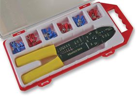
Not much activity on the mending front recently. However, as if to hammer home the point of my previous post, a new shipment of Chinese stuff has needed to be returned. CPC had several things in their special offers and Clearance lists, so I purchased two PIR alarms - exactly the same model that I purchased on Police recommendation some thirteen years ago, but now only £8 instead of £33. Also there was a Crimping Tool Kit which had metric bolt cutting slots for 2mm to 5mm screws, and my old one is only suited for BA threads. With a selection of crimp connectors and a carrying case, the kit was less than £3.50. I also needed some AA batteries (for the alarms etc) and they were offering a 32-pack of Philips ones for around £7.

The stuff came promptly but was a disappointment. One of the PIR alarms was fine but the other proved to be missing a connector strip in the battery compartment, so could not be used at all. So much for the QC inspection sticker...! Of the 32 batteries, five were leaking and partially discharged and as it was a sealed batch, I didn't trust the others - especially as they were going into the alarms for perhaps a year. The expiry date on each battery was October 2017. The rather weak crimp tool was completely Imperial and had nothing metric about it - all cutting points had American wire gauge designations and the AF threads in the bolt cutters would not accept metric screws. The crimp connectors seem flimsy and looked as though the PVC insulation would split when crimped, and finally both latches were broken off the case so it couldn't be closed.
Result: it all has to go back and we start again. I will accept a replacement PIR as they are usually good; the Crimp Kit was described as "metric" but probably isn't even available as such, and I will definitely be going for a different brand of batteries. My experience of Duracell is that even when discharged they don't leak (even though they too may be Chinese sourced, who knows). Maybe in time I will learn that a bargain is not a bargain unless it's a good product for a lower price than usual, and that bad products sold for their actual value are not a good investment.
================
UPDATE 11 July 2014
================
Given two apparently working PIR alarms, I installed them with confidence. After a few months, one has proved to be hard to use as the button action needs a really hard press, and the other has simply decided to sound off whenever it feels the need - even locked in a shed with no movement (and no insects or air currents etc). I should have known...serves me right.
===================================
When I was helping my father-in-law repair his garden shed, I leaned on the arm of his garden bench which promptly snapped off. The wood was rotten around the mounting bolt. I was intending to cut it out and let in a new patch of hardwood, but decided it was easier to replace the whole part with a new one in good pine. Having made a new bracket with the requisite holes, counterbores and such I soaked it all in wood preserver and gave it two coats of fence paint. It should now outlast the rest of the bench, and probably both my father-in-law and me too.
The stuff came promptly but was a disappointment. One of the PIR alarms was fine but the other proved to be missing a connector strip in the battery compartment, so could not be used at all. So much for the QC inspection sticker...! Of the 32 batteries, five were leaking and partially discharged and as it was a sealed batch, I didn't trust the others - especially as they were going into the alarms for perhaps a year. The expiry date on each battery was October 2017. The rather weak crimp tool was completely Imperial and had nothing metric about it - all cutting points had American wire gauge designations and the AF threads in the bolt cutters would not accept metric screws. The crimp connectors seem flimsy and looked as though the PVC insulation would split when crimped, and finally both latches were broken off the case so it couldn't be closed.
Result: it all has to go back and we start again. I will accept a replacement PIR as they are usually good; the Crimp Kit was described as "metric" but probably isn't even available as such, and I will definitely be going for a different brand of batteries. My experience of Duracell is that even when discharged they don't leak (even though they too may be Chinese sourced, who knows). Maybe in time I will learn that a bargain is not a bargain unless it's a good product for a lower price than usual, and that bad products sold for their actual value are not a good investment.
================
UPDATE 11 July 2014
================
Given two apparently working PIR alarms, I installed them with confidence. After a few months, one has proved to be hard to use as the button action needs a really hard press, and the other has simply decided to sound off whenever it feels the need - even locked in a shed with no movement (and no insects or air currents etc). I should have known...serves me right.
===================================
When I was helping my father-in-law repair his garden shed, I leaned on the arm of his garden bench which promptly snapped off. The wood was rotten around the mounting bolt. I was intending to cut it out and let in a new patch of hardwood, but decided it was easier to replace the whole part with a new one in good pine. Having made a new bracket with the requisite holes, counterbores and such I soaked it all in wood preserver and gave it two coats of fence paint. It should now outlast the rest of the bench, and probably both my father-in-law and me too.
Tuesday, 16 April 2013
Chinese quality tools [Rotacraft and Proxxon accessories]
I own a Proxxon FBS 240/E multi-tool, similar to the Dremel, which I find very useful. I'm pretty happy with the quality and I've got a number of other Proxxon products as a result. In general they are well made, which is as well because they aren't particularly cheap. I've had to do a little fettling to the metalwork but nothing serious. They are supposed to be made in Germany and until the other day I had not seen any obvious clones, which is usually a sure indication that badge-engineering of far-eastern products is taking place. My tool holder uses a suction base with a spherical mount, and this particular model is no longer sold by Proxxon - they changed to a conventional clamp base - but the FMZ table vice is available with the clamp and also still with the suction base as the FMS 75. I was therefore surprised to see a very similar item being sold by Draper. I don't know whether this is the same thing from a common supplier, or a copy from China or elsewhere. It looks the same though, and is in the same price range, so it may be German. The fettling on my tool holder, by the way, was that I had to file away a casting seam and the paint from the ball to allow it rotate smoothly. The current production has the ball properly cleaned up with no paint and a smooth spherical surface. On the whole, at this price and quality I think these are European, because you can get something similar for only a few pounds - and which really IS rubbish.
The lesson I have learned finally, after repeated bad experience, is that it simply is not worth buying cheap tools. They are cheap for a reason, and if a tool won't match up to its job then it is worse than useless (because it may do damage). Many years ago I got a cheap set of Allen keys - early Chinese imports - and the first time I used them they simply twisted like sugar candy canes. A good Allen key will break before it bends, and even then not until it has been stressed far beyond the usual requirements. Cheap screwdrivers or bits will twist and damage the screw head. My first sharpening stone ('oil stone') wore away like chalk and when I added oil, it dissolved. I recently purchased a 1/2" twist drill bit from Machine Mart and had to return it due to the visible bend in it; the replacement was also slightly bent but not sufficiently to render it unusable for my application. In future I will only buy industrial quality drills from English, German or American manufacturers. Properly used, they will outlast my lifetime.
Anyway - back to the multi-tool - although the supplied accessories were OK there was only a limited selection, so when I saw a Rotacraft 400-piece accessory kit on offer I decided to have one, so that I would have pretty well everything I might need in a hurry. I should have known - the same kit is available under the Duratool brand, but missing lots of cutting discs and sold as a 150-piece kit. The swanky display box broke within minutes. This is a dead cert for a Chinese import, and unfortunately I paid the penalty. The first time I needed a micro drill I was drilling polypropylene plastic - not exactly a taxing job - and the drill simply refused to penetrate. The next size up was not much better but did drill a hole of sorts. I had a close look at the drill tip and it was off centre and had a flat across the tip - it wouldn't even make a good nail as it isn't hard enough or sharp enough. I also noted that one of the grinding wheels was incomplete and the rest were anything but round. I suppose you could dress them to be concentric, but I fear that they probably won't be much use even then.
![]() |
| The Proxxon FMS 75 vice... |
![]() |
| ...and Snap! But I quite like the blue. |
The lesson I have learned finally, after repeated bad experience, is that it simply is not worth buying cheap tools. They are cheap for a reason, and if a tool won't match up to its job then it is worse than useless (because it may do damage). Many years ago I got a cheap set of Allen keys - early Chinese imports - and the first time I used them they simply twisted like sugar candy canes. A good Allen key will break before it bends, and even then not until it has been stressed far beyond the usual requirements. Cheap screwdrivers or bits will twist and damage the screw head. My first sharpening stone ('oil stone') wore away like chalk and when I added oil, it dissolved. I recently purchased a 1/2" twist drill bit from Machine Mart and had to return it due to the visible bend in it; the replacement was also slightly bent but not sufficiently to render it unusable for my application. In future I will only buy industrial quality drills from English, German or American manufacturers. Properly used, they will outlast my lifetime.
Anyway - back to the multi-tool - although the supplied accessories were OK there was only a limited selection, so when I saw a Rotacraft 400-piece accessory kit on offer I decided to have one, so that I would have pretty well everything I might need in a hurry. I should have known - the same kit is available under the Duratool brand, but missing lots of cutting discs and sold as a 150-piece kit. The swanky display box broke within minutes. This is a dead cert for a Chinese import, and unfortunately I paid the penalty. The first time I needed a micro drill I was drilling polypropylene plastic - not exactly a taxing job - and the drill simply refused to penetrate. The next size up was not much better but did drill a hole of sorts. I had a close look at the drill tip and it was off centre and had a flat across the tip - it wouldn't even make a good nail as it isn't hard enough or sharp enough. I also noted that one of the grinding wheels was incomplete and the rest were anything but round. I suppose you could dress them to be concentric, but I fear that they probably won't be much use even then.
| Cunningly designed to not drill holes... |
| ...or be any use at all. |
The fact is, that if a tool is sourced from China or elsewhere and is cheap, it probably is worth only its price. The Chinese can certainly produce the highest quality goods - they couldn't get a space rocket to the moon using rubbish tools - but so can we, and they cost good money. Given that everything we buy from foreign suppliers has to be paid for by selling something else to them or by borrowing money (probably from them), I would prefer to buy quality tools whose price will go back into the European economy whenever I can afford it. This means doing lot more research into the actual source of the things I buy, and whether they are fairly priced or overpriced, but in the end it is worth it.
Friday, 22 March 2013
Cyclones don't suck [Dyson DC07 HEPA]
I have a workshop and a small shed, and I wanted to move my Compound Mitre Saw into the small shed. As all the machines in the workshop are currently sharing a single dust extractor, I needed to provide a second one for the saw and - prices being what they are - I thought to make use of an old cylinder vacuum cleaner which I have around. I've fitted an extra (cyclonic) cylinder in series with the main extractor, to catch most of the chips and sawdust before they fill the can, and I thought to do the same with the second unit, when it occurred to me that I could get an old broken cyclonic vacuum cleaner and use just the body for the purpose. It would undoubtedly be more efficient than my home-made one. Accordingly I scoured eBay and ended up buying a broken Dyson DC07 HEPA for 99p, being first made to understand by the seller that there was 'a tube missing' - which I could see from the photo, as it didn't seem to have the small bent duct from the base unit to the handle assembly (just visible bottom left in the photo, above the wheel).
I found someone on eBay selling the relevant spare part for a few pounds and won it just in time to collect the broken Dyson. Unfortunately, as sometimes happens, the Dyson wasn't quite as described in that the seller didn't know much about it - when I got it home the 'missing tube' was in a bag of bits and in good condition. After some consideration I asked the seller of the spare tube not to send it and to refund me only the postage costs, keeping the sale price for his trouble and being able to re-sell it. That way he got to sell it twice and I paid out less than I would have done in the end.
The next job was to see what was really wrong with the Dyson. Two things stood out - one, the motor filter was totally clogged up and two, the top of the cyclone unit (the top of the 'rocket exhaust stack') was detached, with all three mounting pillars broken off. This was a setback because the cyclone housing needs to be air-tight and also, the top incorporates a handle which is so placed as to be exactly over the centre of gravity - so is used as a lifting handle to move the machine around even if its main purpose is to lift the dust container. Which is probably why it broke! There are quite a few people selling new cyclones, or clones of them, and there must be a reason for the market - they keep breaking. Unfortunately a new cyclone top would be over £30.
The motor seemed to be fine and all the parts were now present. If I had wanted to buy a new cyclone I could have done so without buying the whole cleaner and so I wondered whether perhaps the Dyson could be resurrected and provide the whole solution - needing no filters or bags and taking up less space than my old cylinder vacuum.
I cleaned up the whole machine after disassembling it. One problem was that the dust container was full and as the release catch was on the top of the cyclone - which was detached - it couldn't be opened. I had to do a lot of judicious fiddling with long sticks to release the catch, after which it was straightforward. The filters are washable foam, and new ones are easily available anyway but these came up fine. I had to free off some of the rollers on the base which had rusted up and also clean out all the nooks and crannies and the brush rollers, but that all went fine. Turning to the broken cyclone, it was obviously a case of having to reattach the three plastic pillars which had broken off the lower part (they were still held by the screws to the upper part), but I found that I was not the first to try and they were fairly mangled and covered in superglue. Clearly simply re-gluing them was not an option - the originals were not strong enough and certainly the glued broken ones weren't. The entire weight of the machine is lifted through those three small screws.
I began by cleaning up the parts with a sharp knife and files until they were back to their normal profile although not altogether complete. At this point I wanted to use epoxy putty to mould a strong buttress round each one, but the pillars are very close to the edge of the housing and there needed to be clearance for the flange on the top part to slide down between the pillars and the outside of the housing, to provide location and a seal - so the repaired pillar had to be much the same size as the old one but stronger. On the other side, the pillars were next to the air passages out of some of the cyclone chambers, which have to be clear for the thing to work at all. The heavier debris drops out of the airstream as it comes into the side of the dust chamber, then the remaining air with the smallest particles flows up into a plenum chamber where it is distributed between the eight mini-cyclones (the 'rocket exhaust' features). Each of these speeds up its part of the airflow until the dust shoots out of the top and falls through the middle into the dust container whilst the air returns to the motor fan through another tube. This is the same action as a normal cyclonic separator but is physically upside-down on this machine. They usually point downwards. Anyway, I refixed the broken stubs together with superglue just to locate them, then wound some wire around each pillar until it provided a continuous collar up the neck a bit like the native African tribe whose womenfolk used to wear stacks of metal rings to stretch their necks. Then I coated the whole pillar with epoxy glue, warming it slightly so that it became runny and soaked between the wire coils. It was necessary to provide a reinforcing collar of some kind because the threaded screw holes had become split and would not have secured the screws for more than a few threads at most. Once all this lot was fully cured, I applied a small amount of epoxy putty (Milliput) where there were gaps and moulded it smoothly back to the original contour of the pillar, with the screws in place but well greased. When it was set the screws could be removed and left a good thread set into a metal-reinforced pillar. As a result, the cyclone housing is now secure and the machine can be lifted by its handle - although I don't do it if I don't have to, just in case.
After reassembling the cleaner it seems to work quite well although the suction is nothing like it is claimed to be in the Dyson ads. As the brushes are good and the whole cleaner is basically serviced, I have to say that there is only one thing left. Some clown has superglued the cover accessing the HEPA filter (possibly because it kept coming loose) which means I can't get into it to replace the filter. Judging by the state of the rest of the machine, this filter is probably clogged solid and is covering the whole of the air outlet from the motor, so is blocking the whole operation. Although it will work OK as a sawdust collector as it is, I think I will need to cut open the filter housing and replace the filter, securing the housing by some other method (magnets?). I'll update the blog if/when I do this. Maybe it will be of more use in the house.....but then I'll be back where I began.....but whatever the outcome, a Dyson for 99p outlay is a bargain.
==================
UPDATE 11 July 2014
==================
I eventually cracked open the HEPA filter housing without having to cut it, and the filter was indeed almost solid. Fitting a new filter and seal restored the performance expected of a Dyson and my smile is even broader. The rest of the repair has held up successfully, so far.
I found someone on eBay selling the relevant spare part for a few pounds and won it just in time to collect the broken Dyson. Unfortunately, as sometimes happens, the Dyson wasn't quite as described in that the seller didn't know much about it - when I got it home the 'missing tube' was in a bag of bits and in good condition. After some consideration I asked the seller of the spare tube not to send it and to refund me only the postage costs, keeping the sale price for his trouble and being able to re-sell it. That way he got to sell it twice and I paid out less than I would have done in the end.
The next job was to see what was really wrong with the Dyson. Two things stood out - one, the motor filter was totally clogged up and two, the top of the cyclone unit (the top of the 'rocket exhaust stack') was detached, with all three mounting pillars broken off. This was a setback because the cyclone housing needs to be air-tight and also, the top incorporates a handle which is so placed as to be exactly over the centre of gravity - so is used as a lifting handle to move the machine around even if its main purpose is to lift the dust container. Which is probably why it broke! There are quite a few people selling new cyclones, or clones of them, and there must be a reason for the market - they keep breaking. Unfortunately a new cyclone top would be over £30.
The motor seemed to be fine and all the parts were now present. If I had wanted to buy a new cyclone I could have done so without buying the whole cleaner and so I wondered whether perhaps the Dyson could be resurrected and provide the whole solution - needing no filters or bags and taking up less space than my old cylinder vacuum.
I cleaned up the whole machine after disassembling it. One problem was that the dust container was full and as the release catch was on the top of the cyclone - which was detached - it couldn't be opened. I had to do a lot of judicious fiddling with long sticks to release the catch, after which it was straightforward. The filters are washable foam, and new ones are easily available anyway but these came up fine. I had to free off some of the rollers on the base which had rusted up and also clean out all the nooks and crannies and the brush rollers, but that all went fine. Turning to the broken cyclone, it was obviously a case of having to reattach the three plastic pillars which had broken off the lower part (they were still held by the screws to the upper part), but I found that I was not the first to try and they were fairly mangled and covered in superglue. Clearly simply re-gluing them was not an option - the originals were not strong enough and certainly the glued broken ones weren't. The entire weight of the machine is lifted through those three small screws.
I began by cleaning up the parts with a sharp knife and files until they were back to their normal profile although not altogether complete. At this point I wanted to use epoxy putty to mould a strong buttress round each one, but the pillars are very close to the edge of the housing and there needed to be clearance for the flange on the top part to slide down between the pillars and the outside of the housing, to provide location and a seal - so the repaired pillar had to be much the same size as the old one but stronger. On the other side, the pillars were next to the air passages out of some of the cyclone chambers, which have to be clear for the thing to work at all. The heavier debris drops out of the airstream as it comes into the side of the dust chamber, then the remaining air with the smallest particles flows up into a plenum chamber where it is distributed between the eight mini-cyclones (the 'rocket exhaust' features). Each of these speeds up its part of the airflow until the dust shoots out of the top and falls through the middle into the dust container whilst the air returns to the motor fan through another tube. This is the same action as a normal cyclonic separator but is physically upside-down on this machine. They usually point downwards. Anyway, I refixed the broken stubs together with superglue just to locate them, then wound some wire around each pillar until it provided a continuous collar up the neck a bit like the native African tribe whose womenfolk used to wear stacks of metal rings to stretch their necks. Then I coated the whole pillar with epoxy glue, warming it slightly so that it became runny and soaked between the wire coils. It was necessary to provide a reinforcing collar of some kind because the threaded screw holes had become split and would not have secured the screws for more than a few threads at most. Once all this lot was fully cured, I applied a small amount of epoxy putty (Milliput) where there were gaps and moulded it smoothly back to the original contour of the pillar, with the screws in place but well greased. When it was set the screws could be removed and left a good thread set into a metal-reinforced pillar. As a result, the cyclone housing is now secure and the machine can be lifted by its handle - although I don't do it if I don't have to, just in case.
After reassembling the cleaner it seems to work quite well although the suction is nothing like it is claimed to be in the Dyson ads. As the brushes are good and the whole cleaner is basically serviced, I have to say that there is only one thing left. Some clown has superglued the cover accessing the HEPA filter (possibly because it kept coming loose) which means I can't get into it to replace the filter. Judging by the state of the rest of the machine, this filter is probably clogged solid and is covering the whole of the air outlet from the motor, so is blocking the whole operation. Although it will work OK as a sawdust collector as it is, I think I will need to cut open the filter housing and replace the filter, securing the housing by some other method (magnets?). I'll update the blog if/when I do this. Maybe it will be of more use in the house.....but then I'll be back where I began.....but whatever the outcome, a Dyson for 99p outlay is a bargain.
==================
UPDATE 11 July 2014
==================
I eventually cracked open the HEPA filter housing without having to cut it, and the filter was indeed almost solid. Fitting a new filter and seal restored the performance expected of a Dyson and my smile is even broader. The rest of the repair has held up successfully, so far.
Sunday, 17 March 2013
Prolonging life [Currys by Koss HP7022 headphones]
Back in the Dark Ages (1970s) I was looking for a set of hi-fi headphones and was shown these, badged from Currys but made by Koss - I was a bit sceptical because I had never seen open-backed over-the-ear phones with only a sponge ring as a cushion, but they delivered good solid bass and were really comfortable. I don't recall the price but at the time it was quite a bit for my limited budget. In fact since then I've come to realise that maybe the bass is a bit heavy, but it isn't boomy and resonant like some, so I like the sound.
They have a 1/4" stereo jack plug on a self-coiled cable which gradually lost its spring. It still just about self-coils but can't support its own weight any more, so it dribbles down from the hi-fi onto the floor and back up to my ear. There is a simple barely-padded headband and the transducers are circular and very plain. The cushions were simple rings of foam plastic and didn't do any acoustic sealing (as befits an open transducer), and when one transducer failed many years ago the replacement from Koss had no padding and I had to transfer the foam over, which was annoying as it was glued on. There is no overall shell, just the sealed transducer with a foam ring stuck to the front and a plastic cover on the back to mount it and cover the wire terminals. The headband adjustment is done by the transducers being gimballed on a serrated aluminium strip which slides through a gap in a plastic block. Somewhere in the block there is a detent of some sort, metal or plastic, which rubs the serrations and jams the strip wherever you leave it. Actually, they aren't much different in style than ex-GPO telephone receivers from WW2. Over the years the play between the strip and the detent grew until I could put the headband over my skull and the transducers would each drop with a clunk down to their lowest position. And then, eventually, the foam started to decompose and turn to dust until I had to simply strip it off. But they still sounded so good that I wore them anyway, which is pretty uncomfortable because the transducers have a domed front which pokes your lughole painfully.
Recently I finally decided to chuck them out, having lots of others, but still.....they sounded so nice....and they were very familiar....you know the story, of course I kept them. I looked around eBay and found some ear cushions which were intended for an AKG K81DJ set - simply circular (toroidal). Although not meant to be glued on, these have a flat back face and can be glued successfully with Copydex latex adhesive. And they were the right size, 75mm diameter. They look fine and work very well in the lug protection role. The loose adjustment was awkward as the little housings are riveted and to get into them I would have had to destroy the outside face. Instead I found a couple of very strong tension springs about 10mm long, with looped ends, and stretched them across the face of the strip on each side and wired them behind the headband. This has the effect of holding the strip against the detent inside its housing regardless of the other clearances and is almost invisible (apart from the white ties, which I will change when I have something brown).
I can't do much about the cable without replacing it completely so I shall live with the existing one, at least giving me the advantage of being able to walk across the room without it unplugging itself. Not much work involved but it means that my favourite headphones can continue to give me pleasure for a few more years. And that's probably all I've got myself anyway!
They have a 1/4" stereo jack plug on a self-coiled cable which gradually lost its spring. It still just about self-coils but can't support its own weight any more, so it dribbles down from the hi-fi onto the floor and back up to my ear. There is a simple barely-padded headband and the transducers are circular and very plain. The cushions were simple rings of foam plastic and didn't do any acoustic sealing (as befits an open transducer), and when one transducer failed many years ago the replacement from Koss had no padding and I had to transfer the foam over, which was annoying as it was glued on. There is no overall shell, just the sealed transducer with a foam ring stuck to the front and a plastic cover on the back to mount it and cover the wire terminals. The headband adjustment is done by the transducers being gimballed on a serrated aluminium strip which slides through a gap in a plastic block. Somewhere in the block there is a detent of some sort, metal or plastic, which rubs the serrations and jams the strip wherever you leave it. Actually, they aren't much different in style than ex-GPO telephone receivers from WW2. Over the years the play between the strip and the detent grew until I could put the headband over my skull and the transducers would each drop with a clunk down to their lowest position. And then, eventually, the foam started to decompose and turn to dust until I had to simply strip it off. But they still sounded so good that I wore them anyway, which is pretty uncomfortable because the transducers have a domed front which pokes your lughole painfully.
Recently I finally decided to chuck them out, having lots of others, but still.....they sounded so nice....and they were very familiar....you know the story, of course I kept them. I looked around eBay and found some ear cushions which were intended for an AKG K81DJ set - simply circular (toroidal). Although not meant to be glued on, these have a flat back face and can be glued successfully with Copydex latex adhesive. And they were the right size, 75mm diameter. They look fine and work very well in the lug protection role. The loose adjustment was awkward as the little housings are riveted and to get into them I would have had to destroy the outside face. Instead I found a couple of very strong tension springs about 10mm long, with looped ends, and stretched them across the face of the strip on each side and wired them behind the headband. This has the effect of holding the strip against the detent inside its housing regardless of the other clearances and is almost invisible (apart from the white ties, which I will change when I have something brown).
I can't do much about the cable without replacing it completely so I shall live with the existing one, at least giving me the advantage of being able to walk across the room without it unplugging itself. Not much work involved but it means that my favourite headphones can continue to give me pleasure for a few more years. And that's probably all I've got myself anyway!
Wednesday, 13 March 2013
Scrap from the sixties [Moulton Deluxe M2]
Some time ago - more than twelve years - I acquired a rusty old bicycle. It's so long ago that I can't remember the exact circumstances but I think it was found in a rubbish skip beside my place of work, having been added overnight by an opportunistic fly-tipper. I recognised it as a Moulton bike which was a bit of a fashion icon in the sixties, and I knew it had rubber suspension to both wheels which made it interesting. So I put it on one side for future attention; and now the future seems to be here.
The Moulton was a revolution for its day, being the first small-wheeled "shopper" bike. In fact it wasn't designed solely as a shopper, although they excel in that role. The small 16" wheels had very high pressure narrow tyres to minimise the rolling resistance, and the suspension was designed to compensate for the otherwise hard ride. The whole bike was designed from the ground up for efficiency and practicality and the result was a machine which, despite its innovative and very odd appearance, was able to outperform conventional bicycles - including touring and sports models - in every area. Unfortunately Raleigh didn't take kindly to the new upstart and being unable to replicate the design, produced their own version of a shopper with low-pressure balloon tyres and which lacking all of the unique features except the odd appearance, was inefficient, cheap and nasty. The problem was that it was cheap and the public didn't understand the difference, so they bought it in droves. In the end Raleigh bought out Moulton and took over manufacture and after a few years they dropped the Moulton products completely. Fortunately the designer, Dr. Alex Moulton, was able to re-acquire the patent rights later on and Moulton bikes continued to be developed and are still being made today. Now, however, they are very sophisticated and high quality, and can cost anywhere between £940 and £11000 each - a far cry from the £30-odd which a Moulton would have cost in 1963. Regrettably Dr. Moulton, who also designed the rubber suspension for the original Mini, died in November 2012 but his revolutionary designs are very much alive.
My rusty pile was clearly one of the original models but as so many variations were made, I needed to find out more. I purchased a copy of "The Moulton Bicycle" by Tony Hadland, which comprehensively tells the story of the Moulton Bicycle Company. From that I deduced that I had probably got a Standard or Deluxe from the mid-sixties - mine has a rear carrier but has been slathered copiously in blue Hammerite paint, which makes it hard to establish the original colour scheme or model name. However it had had chromed steel mudguards and a four-speed Sturmey-Archer FW hub gear, which were clues. I recently got a new copy of "The 'classic' Moulton" by Paul Grogan, not a cheap book but absolutely the best reference available. It shows full details of every Moulton F-frame model, colour and component that Moulton and Raleigh ever produced, with drawings and photographs and including restoration procedures, and I cannot recommend it highly enough to anyone interested in Moultons. This has enabled me to determine that I seem to have a Series One F-frame machine built at the Kirkby (Liverpool) factory in or around November 1964 (week 48) and was the 87th machine built that week (serial number 480087). It is likely to be a Deluxe M2 model but has lost its front carrier, its Moulton branded bell, its rear carrier bag and its original saddle, and has acquired a sprung mattress saddle, an anonymous bell and (possibly) non-standard brake callipers. The front calliper is unbranded and the rear one doesn't match those in the book. It has a short chromed steel chain guard and the unique optional long side stand. Everything is rusty and crusty; there is slight play in the steering and the rear suspension block is becoming unbonded. However it looks as though the frame and all the steel components are basically sound. At this point it looks depressingly likely that I will be driven to restore this bike to its original condition because there aren't that many around and it's so interesting, and it is an example of a machine which really was revolutionary. There are quite a few useful re-manufactured spare parts available for them so the quest is now on to locate the missing items if possible. It may take a few years and a lot of money - but I would really like to see this one looking as it came from the showroom.
The Moulton was a revolution for its day, being the first small-wheeled "shopper" bike. In fact it wasn't designed solely as a shopper, although they excel in that role. The small 16" wheels had very high pressure narrow tyres to minimise the rolling resistance, and the suspension was designed to compensate for the otherwise hard ride. The whole bike was designed from the ground up for efficiency and practicality and the result was a machine which, despite its innovative and very odd appearance, was able to outperform conventional bicycles - including touring and sports models - in every area. Unfortunately Raleigh didn't take kindly to the new upstart and being unable to replicate the design, produced their own version of a shopper with low-pressure balloon tyres and which lacking all of the unique features except the odd appearance, was inefficient, cheap and nasty. The problem was that it was cheap and the public didn't understand the difference, so they bought it in droves. In the end Raleigh bought out Moulton and took over manufacture and after a few years they dropped the Moulton products completely. Fortunately the designer, Dr. Alex Moulton, was able to re-acquire the patent rights later on and Moulton bikes continued to be developed and are still being made today. Now, however, they are very sophisticated and high quality, and can cost anywhere between £940 and £11000 each - a far cry from the £30-odd which a Moulton would have cost in 1963. Regrettably Dr. Moulton, who also designed the rubber suspension for the original Mini, died in November 2012 but his revolutionary designs are very much alive.
| My skip find |
My rusty pile was clearly one of the original models but as so many variations were made, I needed to find out more. I purchased a copy of "The Moulton Bicycle" by Tony Hadland, which comprehensively tells the story of the Moulton Bicycle Company. From that I deduced that I had probably got a Standard or Deluxe from the mid-sixties - mine has a rear carrier but has been slathered copiously in blue Hammerite paint, which makes it hard to establish the original colour scheme or model name. However it had had chromed steel mudguards and a four-speed Sturmey-Archer FW hub gear, which were clues. I recently got a new copy of "The 'classic' Moulton" by Paul Grogan, not a cheap book but absolutely the best reference available. It shows full details of every Moulton F-frame model, colour and component that Moulton and Raleigh ever produced, with drawings and photographs and including restoration procedures, and I cannot recommend it highly enough to anyone interested in Moultons. This has enabled me to determine that I seem to have a Series One F-frame machine built at the Kirkby (Liverpool) factory in or around November 1964 (week 48) and was the 87th machine built that week (serial number 480087). It is likely to be a Deluxe M2 model but has lost its front carrier, its Moulton branded bell, its rear carrier bag and its original saddle, and has acquired a sprung mattress saddle, an anonymous bell and (possibly) non-standard brake callipers. The front calliper is unbranded and the rear one doesn't match those in the book. It has a short chromed steel chain guard and the unique optional long side stand. Everything is rusty and crusty; there is slight play in the steering and the rear suspension block is becoming unbonded. However it looks as though the frame and all the steel components are basically sound. At this point it looks depressingly likely that I will be driven to restore this bike to its original condition because there aren't that many around and it's so interesting, and it is an example of a machine which really was revolutionary. There are quite a few useful re-manufactured spare parts available for them so the quest is now on to locate the missing items if possible. It may take a few years and a lot of money - but I would really like to see this one looking as it came from the showroom.
Monday, 11 March 2013
Work in progress [Dawes Red Feather]
A while ago, I came across a bike which had been left behind by a departing University student. It had been mangled in an accident and left for dead, but it seemed in good condition otherwise and was a Dawes alloy framed hybrid. I had a Dawes Windsor tourer until recently - a lovely bike, handbuilt frame and decent components, but it had dropped handlebars and a non-indexing gear shift and I wanted something more like a mountain bike. So when I saw the redundant Dawes languishing I decided to see if it could be saved.
It's a Dawes Red Feather, like the one in the photo, but oddly it seems hard to find information about them. All the web searches come up with the latest Red Feather version, unlike this one, or a vintage fifties model again unlike this. This one is a hybrid with 700C rims, 7 speed Shimano derailleur with a granny gear and modern handlebars with an indexed short twist-grip shifter. The brakes are centre-pull callipers, the frame is a chunky alloy hand-built with oval section down-tube. It was just what I wanted but I have no idea when or where it was made.
The bike had certainly had a hard bump - the derailleur mechanism was damaged and the drop-out was bent out at an angle, the back wheel was buckled and the front mudguard was shattered, and there is a chunk out of the crank spider. However after a clean-up it seemed worth a try.
The first problem was the drop-out. If it couldn't be successfully straightened then I might as well give up immediately. As it came out, I was able to apply leverage with a scaffold pole (strong and five feet long) and the drop-out realigned without breaking. The derailleur had to be replaced and after a detour caused by someone selling me one which operated the wrong way round, I eventually got a suitable new unit for £25. The buckled wheel cost me £8 to find out that it was really beyond repair, but adjusting the spoke tensions has given me a straightish wheel which might do to make a trailer or some other light duty function. The new rear wheel cost £30 and some rim tape £2.50, then it was just a matter of transferring the gear set and the tyre. It looks as though a new mudguard set to match will be around £12; the crank spider is perfectly usable although it will probably be replaced at some point. The saddle has been replaced by a Lepper leather one which has yet to be moulded to my contours, so that's something to look forward to (not). Otherwise the bike is in much the same condition as the one in the photo and I hope to make good use of it. It will be the first bike I've had with an indexed gear change and effective brakes and I'm looking forward to getting out on it this summer. It really is "as light as a feather".
================
UPDATE 11 July 2014
================
I've used the bike for a while and it's great, but it has a problem with occasionally missing a gear. Research has shown that the derailleur set which was sold to me is "suitable for 7/8 speed cassette" but the hysteresis in the changer mechanism means the the exact positioning of the cage is slightly different when changing up through the range than when changing down. This causes one or other of the middle gears to be out of line with the cage so there's a glitch until a slight pressure is put to move the changer up or down from the indexed position, and that usually means jumping over the gear you were trying to select. I can live with that, but it illustrates the difficulties that can arise when you try to mix parts of different gear sets.
It's a Dawes Red Feather, like the one in the photo, but oddly it seems hard to find information about them. All the web searches come up with the latest Red Feather version, unlike this one, or a vintage fifties model again unlike this. This one is a hybrid with 700C rims, 7 speed Shimano derailleur with a granny gear and modern handlebars with an indexed short twist-grip shifter. The brakes are centre-pull callipers, the frame is a chunky alloy hand-built with oval section down-tube. It was just what I wanted but I have no idea when or where it was made.
The bike had certainly had a hard bump - the derailleur mechanism was damaged and the drop-out was bent out at an angle, the back wheel was buckled and the front mudguard was shattered, and there is a chunk out of the crank spider. However after a clean-up it seemed worth a try.
The first problem was the drop-out. If it couldn't be successfully straightened then I might as well give up immediately. As it came out, I was able to apply leverage with a scaffold pole (strong and five feet long) and the drop-out realigned without breaking. The derailleur had to be replaced and after a detour caused by someone selling me one which operated the wrong way round, I eventually got a suitable new unit for £25. The buckled wheel cost me £8 to find out that it was really beyond repair, but adjusting the spoke tensions has given me a straightish wheel which might do to make a trailer or some other light duty function. The new rear wheel cost £30 and some rim tape £2.50, then it was just a matter of transferring the gear set and the tyre. It looks as though a new mudguard set to match will be around £12; the crank spider is perfectly usable although it will probably be replaced at some point. The saddle has been replaced by a Lepper leather one which has yet to be moulded to my contours, so that's something to look forward to (not). Otherwise the bike is in much the same condition as the one in the photo and I hope to make good use of it. It will be the first bike I've had with an indexed gear change and effective brakes and I'm looking forward to getting out on it this summer. It really is "as light as a feather".
================
UPDATE 11 July 2014
================
I've used the bike for a while and it's great, but it has a problem with occasionally missing a gear. Research has shown that the derailleur set which was sold to me is "suitable for 7/8 speed cassette" but the hysteresis in the changer mechanism means the the exact positioning of the cage is slightly different when changing up through the range than when changing down. This causes one or other of the middle gears to be out of line with the cage so there's a glitch until a slight pressure is put to move the changer up or down from the indexed position, and that usually means jumping over the gear you were trying to select. I can live with that, but it illustrates the difficulties that can arise when you try to mix parts of different gear sets.
Friday, 8 March 2013
Simply Sony [Sony TC-FX25]
Today's special is a Sony TC-FX25 stereo cassette deck with no tape movement. The belts were all intact but had sat unused for so long that they had set into oval crispy things, so that was the first port of call.
This is a very straightforward deck - single playing direction, logic controls, manual selection of tape type and Dolby, LED bar graph recording level indicators and those horrid slide pots which were so popular at the time. You need to take off the top case (just a few obvious screws) and the bottom plate, which is held by three screws along the back edge and hooks under the front panel. The tape carrier door slides up and off with the door open. The front panel is clipped into place and just comes off forwards, and you have to disconnect a couple of plugs on the main circuit board to free it by threading the wiring loom out through the chassis. You can re-connect them directly to the PCB and the machine can still be operated, but note that on this old model, the mains transformer is fully exposed with tags carrying mains voltage on the top - I made up a cardboard box to cover the terminals while I was working on it.
To remove the transport mechanism there are four front-facing screws around its edge - coloured dark to distinguish them from any others. I needed to undo a few cable ties before the deck could be taken out, then disconnected some plugs on the main PCB - there are several similar but they are all different numbers of ways, so although I did make a map first, it's difficult to go wrong anyway. I guess it might help any viewer if I were to put in a scan of things like scribble maps, but I'm pushed for time at the moment. If anyone wants more info just stick a comment in.
The back plate with motor comes off easily allowing access to the first two of the four belts in this model. Again, without access to the exact replacement parts you have to do a bit of substitution. I found that the capstan belt was flat section, and CPC Farnell had a suitable one in their AVBELT5 (71mm dia. by 2.8mm wide, 0.5mm thick). The fast-forward belt driving the spools is replaced by an AVBELT76 (37mm dia. by 1.2mm square section). Then the back plate can be re-fitted.
The other two belts are accessed by removing the front plate and tape carrier assembly. This involves taking out a couple of brass screws each side which pivot the stays and I seem to recall there were a couple more at the top or side fixing the plate to the deck frame - but it was all pretty obvious. Once the screws are out, the assembly falls out forwards. It's probably worth keeping it in about the same position as it comes out, to save getting in a 'folding deckchair' pickle when re-fitting. At this point I was able to fit the other two belts - AVBELT69 (32mm dia. by 1.2mm square section) driving the take-up spool carrier, and the tape counter belt AVBELT100 (64mm dia. by 1.2mm square section) from the take-up spool spindle to the counter. As the tape counter is mechanical and still mounted on the main chassis, I left the drive belt loose having threaded it through the metalwork and then I re-fitted the front plate and tape carrier assembly. Throughout all this I made sure that I cleaned and lubricated the heads, pinch wheels and bearings as usual.
After putting it all back together, the tape mechanism worked perfectly with no slipping or wobble. Unfortunately there was only one channel playing and touching the PCB or wiring caused much crackling. Eventually I traced the problem to the tape head connectors - there seemed to be no dry solder joints so I used contact cleaner (Electrolube) on all the connectors, making sure to work them off and on to scrape off any tarnish. This sorted it out and the whole machine is now performing well.
This machine was hi-fi for its day but certainly not anything special, and even fully working it can't outperform any decent bit of kit - it's very basic. Added to that, it's not pristine - one or two rusty scratches - and uses cassettes which are hardly the medium of the future any more. But it has two standard (quarter inch) microphone inputs on the front and is still good for basic recording or transcribing old tapes, so maybe it will find a use somewhere. Anyway, it's satisfying to see it back in working order.
This is a very straightforward deck - single playing direction, logic controls, manual selection of tape type and Dolby, LED bar graph recording level indicators and those horrid slide pots which were so popular at the time. You need to take off the top case (just a few obvious screws) and the bottom plate, which is held by three screws along the back edge and hooks under the front panel. The tape carrier door slides up and off with the door open. The front panel is clipped into place and just comes off forwards, and you have to disconnect a couple of plugs on the main circuit board to free it by threading the wiring loom out through the chassis. You can re-connect them directly to the PCB and the machine can still be operated, but note that on this old model, the mains transformer is fully exposed with tags carrying mains voltage on the top - I made up a cardboard box to cover the terminals while I was working on it.
To remove the transport mechanism there are four front-facing screws around its edge - coloured dark to distinguish them from any others. I needed to undo a few cable ties before the deck could be taken out, then disconnected some plugs on the main PCB - there are several similar but they are all different numbers of ways, so although I did make a map first, it's difficult to go wrong anyway. I guess it might help any viewer if I were to put in a scan of things like scribble maps, but I'm pushed for time at the moment. If anyone wants more info just stick a comment in.
The back plate with motor comes off easily allowing access to the first two of the four belts in this model. Again, without access to the exact replacement parts you have to do a bit of substitution. I found that the capstan belt was flat section, and CPC Farnell had a suitable one in their AVBELT5 (71mm dia. by 2.8mm wide, 0.5mm thick). The fast-forward belt driving the spools is replaced by an AVBELT76 (37mm dia. by 1.2mm square section). Then the back plate can be re-fitted.
The other two belts are accessed by removing the front plate and tape carrier assembly. This involves taking out a couple of brass screws each side which pivot the stays and I seem to recall there were a couple more at the top or side fixing the plate to the deck frame - but it was all pretty obvious. Once the screws are out, the assembly falls out forwards. It's probably worth keeping it in about the same position as it comes out, to save getting in a 'folding deckchair' pickle when re-fitting. At this point I was able to fit the other two belts - AVBELT69 (32mm dia. by 1.2mm square section) driving the take-up spool carrier, and the tape counter belt AVBELT100 (64mm dia. by 1.2mm square section) from the take-up spool spindle to the counter. As the tape counter is mechanical and still mounted on the main chassis, I left the drive belt loose having threaded it through the metalwork and then I re-fitted the front plate and tape carrier assembly. Throughout all this I made sure that I cleaned and lubricated the heads, pinch wheels and bearings as usual.
After putting it all back together, the tape mechanism worked perfectly with no slipping or wobble. Unfortunately there was only one channel playing and touching the PCB or wiring caused much crackling. Eventually I traced the problem to the tape head connectors - there seemed to be no dry solder joints so I used contact cleaner (Electrolube) on all the connectors, making sure to work them off and on to scrape off any tarnish. This sorted it out and the whole machine is now performing well.
This machine was hi-fi for its day but certainly not anything special, and even fully working it can't outperform any decent bit of kit - it's very basic. Added to that, it's not pristine - one or two rusty scratches - and uses cassettes which are hardly the medium of the future any more. But it has two standard (quarter inch) microphone inputs on the front and is still good for basic recording or transcribing old tapes, so maybe it will find a use somewhere. Anyway, it's satisfying to see it back in working order.
Tuesday, 5 February 2013
Towbars & trailers [Breyer 2614 Pick Up Truck]
My 11yo daughter, who is besotted by all things equine, has a Breyer 2614 Dually Pickup Truck - a plastic 1:9 scale generic model to match her (vast) range of Breyer Traditional Scale model horses. She also has a matching Breyer 2615 White Horse Trailer.
The truck has a fitted towbar with a tiny ball hitch, which fits the hitch on the front of the trailer. Unlike most of these toys, the towbar frame is made separately and screwed onto the truck, and amazingly the actual ball is also a separate item - although this wasn't obvious at first.One day after the truck and trailer had been left out as usual on the living room floor in everyone's path, an unidentified vandal stepped on the trailer A-frame, snapping it across and breaking off the top of the towing ball as well. This gave rise to the usual tearful plea for restoration.
This is the combination type of hitch, where in the real world the ball is on the end of a pin which simply drops through a hole in a bracket. This allows the use of a normal 50mm (scale) hitch or the farm type, which is just a steel loop on the trailer - you can lift the pin out and drop it back with the trailer eye in place. Noisy on the road, but secure and simple. In this case I assumed, as you do, that the whole towbar and ball were one moulding so I unscrewed it for repair, without much optimism. When I examined it, I found that firstly the pin part was detachable, and secondly that it has a steel reinforcing pin up the middle - which seems eminently sensible except that it didn't extend up into the ball, rendering the ball liable to break off. Which it did. Normally I would repair something like this by drilling both plastic parts and inserting a metal pin - as they had - but as there already was one, and it was still in the pin moulding, I had to simply glue the ball back in place and hope for the best. I used cyanoacrylate (superglue) but this might not have been the best choice here on reflection. I sourced a round-headed woodscrew of the appropriate size to replace the pin & ball if it broke again. In fact it did break off again almost immediately and the screw is currently in use. Although it's only half a sphere, not a full ball, that doesn't matter as the "hitch" socket on the trailer is just a void under the A-frame, not a shaped socket, so anything that acts like a hook will work after a fashion.
I have retained the parts of the pin and will re-fix them using plastic cement, which should weld the plastic around the steel pin and may be stronger than gluing it all with superglue. I may also try to turn up a new pin and ball from a piece of hard nylon or epoxy putty, which could be more resilient. The thing which surprises me (not really...!) is that the pin is reinforced, is a separate breakable, losable part on a £55 model and yet doesn't seem to be available as a spare part. Maybe they assume that with a steel pin up the middle, they won't break. Well, I have news for them!
The trailer was easier as the A-frame had cracked across where it joined the trailer body, but had not broken off completely. The frame is made of U-channel section plastic so I turned it upside down and clamped it in alignment, then dropped a steel rod into each U-channel and filled the channel with hot-melt glue. That gave a solid frame and was not visible from above. The downside is that it makes the front of the trailer heavier, so it tips forward (next time I'll use alloy). There is an adjustable support leg at the front, like a jockey wheel without a wheel, but if this is allowed to rest on the carpet then any attempt to push the trailer forward will bend it. Some time back I fabricated a swivelling jockey wheel and attached it to this pin, which would have solved the problem if it too had not been shattered by rough usage. So that's on the list for re-making in metal or nylon.
It seems pretty bad form to design and market a model which costs as much as this yet is still made in the same cheap way as most plastic toys, when for the sake of a little more thought or quality control they could make them durable to use. The addition of a jockey wheel on the trailer and a one-piece unbreakable towball/pin would be a step towards the quality you expect at the price.
The truck has a fitted towbar with a tiny ball hitch, which fits the hitch on the front of the trailer. Unlike most of these toys, the towbar frame is made separately and screwed onto the truck, and amazingly the actual ball is also a separate item - although this wasn't obvious at first.One day after the truck and trailer had been left out as usual on the living room floor in everyone's path, an unidentified vandal stepped on the trailer A-frame, snapping it across and breaking off the top of the towing ball as well. This gave rise to the usual tearful plea for restoration.
This is the combination type of hitch, where in the real world the ball is on the end of a pin which simply drops through a hole in a bracket. This allows the use of a normal 50mm (scale) hitch or the farm type, which is just a steel loop on the trailer - you can lift the pin out and drop it back with the trailer eye in place. Noisy on the road, but secure and simple. In this case I assumed, as you do, that the whole towbar and ball were one moulding so I unscrewed it for repair, without much optimism. When I examined it, I found that firstly the pin part was detachable, and secondly that it has a steel reinforcing pin up the middle - which seems eminently sensible except that it didn't extend up into the ball, rendering the ball liable to break off. Which it did. Normally I would repair something like this by drilling both plastic parts and inserting a metal pin - as they had - but as there already was one, and it was still in the pin moulding, I had to simply glue the ball back in place and hope for the best. I used cyanoacrylate (superglue) but this might not have been the best choice here on reflection. I sourced a round-headed woodscrew of the appropriate size to replace the pin & ball if it broke again. In fact it did break off again almost immediately and the screw is currently in use. Although it's only half a sphere, not a full ball, that doesn't matter as the "hitch" socket on the trailer is just a void under the A-frame, not a shaped socket, so anything that acts like a hook will work after a fashion.
I have retained the parts of the pin and will re-fix them using plastic cement, which should weld the plastic around the steel pin and may be stronger than gluing it all with superglue. I may also try to turn up a new pin and ball from a piece of hard nylon or epoxy putty, which could be more resilient. The thing which surprises me (not really...!) is that the pin is reinforced, is a separate breakable, losable part on a £55 model and yet doesn't seem to be available as a spare part. Maybe they assume that with a steel pin up the middle, they won't break. Well, I have news for them!
The trailer was easier as the A-frame had cracked across where it joined the trailer body, but had not broken off completely. The frame is made of U-channel section plastic so I turned it upside down and clamped it in alignment, then dropped a steel rod into each U-channel and filled the channel with hot-melt glue. That gave a solid frame and was not visible from above. The downside is that it makes the front of the trailer heavier, so it tips forward (next time I'll use alloy). There is an adjustable support leg at the front, like a jockey wheel without a wheel, but if this is allowed to rest on the carpet then any attempt to push the trailer forward will bend it. Some time back I fabricated a swivelling jockey wheel and attached it to this pin, which would have solved the problem if it too had not been shattered by rough usage. So that's on the list for re-making in metal or nylon.
It seems pretty bad form to design and market a model which costs as much as this yet is still made in the same cheap way as most plastic toys, when for the sake of a little more thought or quality control they could make them durable to use. The addition of a jockey wheel on the trailer and a one-piece unbreakable towball/pin would be a step towards the quality you expect at the price.
Sunday, 3 February 2013
Disturbing the residents [Tricity Bendix BL501W]
In this case, the residents were the creatures that were living, or had been, under our fridge. We have a built-in fridge of indeterminate ancestry, probably early 1990s, which preserved its anonymity behind a pine door in a row of kitchen units. I eventually found the model plate and it is a Tricity Bendix BL501W larder fridge, which seems to be an obscure one when it comes to getting info.
The fridge came with the house so there is no documentation. As long as it was working, we left it alone, but this turned out to be a mistake. There is no free convection round these for the condenser to lose heat, so the tubes are ventilated by a tangential blower of the type once common in fan heaters - a small induction motor driving a squirrel-cage centrifugal fan about 180mm long and 60mm diameter. I was vaguely uneasy about the fact that the fridge had been in-situ for at least sixteen years without anyone cleaning the fluff out of the coils and latterly it seems to have spent more and more time running rather than resting. This was brought to my attention because of the increasing noise from underneath caused by the fan module rattling, and it was obvious that the fan was out of balance and probably had worn bearings. Eventually it got to the point where it was banging and only intermittently running (although the compressor was still running normally) and I decided that Something Had To Be Done.
Getting access was easy - if I had known how easy, I would have done it years ago! It was screwed to the next cabinet by a bracket with another screw vertically into the worktop above, and a third screw by the top hinge (opposite, on the right in this case). Removing the plinth board from the run of units revealed the most disgusting assortment of dead creatures, live insects and spiders, dust, rotten food, lost implements and even a pile of sand placed by an invading ant colony some time ago. I had to plunge my hands into this lot to lower the adjustable feet, to allow the fridge to slide forward and out. Cleaning out the cavity took another hour.
It was handy to be able to prop the fridge on a support, leaning backwards. The fan module is visible at the front through a clear plastic window which is held in place by two small screws and slides out. Additionally there is a sliding tray at the side which comes out to reveal the bottom of the condenser coils. Other than that, the whole bottom tray is a single plastic moulding with the compressor and other bits fixed in it (and connected by copper pipe to the compartment) so no further dismantling was possible. Inside the coil chamber was a mat of greasy fluff and debris which virtually blocked the whole air passage.
Examining the fan, it was clear that the rotor was completely free at one end and it was obvious that the bearing had disappeared. These things are very simple and have only the motor spindle supporting them at one end and at the other end the shaft is running in a graphite sleeve bearing - a graphite bush with a metal thrust plate moulded in, the whole bush being supported in a very flexible rubber grommet in the pressed steel chassis. In fact the graphite bush was still there, but had worn oversize to the point where it didn't show in its housing. I gloss over the half an hour it took to work out how to get the fan module out of its rubber mountings and extricated through the front opening - I had to use a big screwdriver and a big pry bar to lever it out of the moulded tray, bending the mounting lugs on the way. If there's an easier way, please tell me.
Unfortunately it seems that these fans are not as common as they used to be. The only place I could find them (without troubling the Electrolux service people, as I don't want to be laughed at) was at Catering Parts UK, whose model TAS18R seems to be suitable. Unfortunately it's also £32, which isn't viable as we will probably only need this fridge for a few more months. So the next step was to find a bearing - also with no success. In the end, I selected a small piece of old oak, which is very hard, and turned a new bush on the lathe. I have successfully used old oak bearings before, in a kids' scooter, and it has been running for over five years with no obvious wear. You do need to grease it first though. The oak sleeve fitted the grommet OK but I had to fill the grommet with silicone sealant, as the rubber was perished and began to fall apart. After a suitable curing period, the oak bush was greased and put in place and the fan reassembled, and works perfectly with a very smooth action.
I had to repair some of the door frame which had been kicked to bits, and clean off a horrible mess of cheesy layers and fungal growth where spilt milk had been trapped in the fascia, then it was time to force the fan module back in. I eventually succeeded, and the fridge is now back in use and running quietly. Very quietly in fact, because I haven't seen the fan rotor move since installation. The fridge is maintaining temperature correctly, the condenser barely gets warm and I don't know whether the fan is off because it simply isn't needed or whether I have knocked off a wire during the violent re-installation. At the moment I'm not going to investigate further, as everyone is happy and the dog can sleep undisturbed at night. But it keeps nagging away at me, and maybe next year I'll pull it out again just to see if I did screw it up.
The fridge came with the house so there is no documentation. As long as it was working, we left it alone, but this turned out to be a mistake. There is no free convection round these for the condenser to lose heat, so the tubes are ventilated by a tangential blower of the type once common in fan heaters - a small induction motor driving a squirrel-cage centrifugal fan about 180mm long and 60mm diameter. I was vaguely uneasy about the fact that the fridge had been in-situ for at least sixteen years without anyone cleaning the fluff out of the coils and latterly it seems to have spent more and more time running rather than resting. This was brought to my attention because of the increasing noise from underneath caused by the fan module rattling, and it was obvious that the fan was out of balance and probably had worn bearings. Eventually it got to the point where it was banging and only intermittently running (although the compressor was still running normally) and I decided that Something Had To Be Done.
Getting access was easy - if I had known how easy, I would have done it years ago! It was screwed to the next cabinet by a bracket with another screw vertically into the worktop above, and a third screw by the top hinge (opposite, on the right in this case). Removing the plinth board from the run of units revealed the most disgusting assortment of dead creatures, live insects and spiders, dust, rotten food, lost implements and even a pile of sand placed by an invading ant colony some time ago. I had to plunge my hands into this lot to lower the adjustable feet, to allow the fridge to slide forward and out. Cleaning out the cavity took another hour.
It was handy to be able to prop the fridge on a support, leaning backwards. The fan module is visible at the front through a clear plastic window which is held in place by two small screws and slides out. Additionally there is a sliding tray at the side which comes out to reveal the bottom of the condenser coils. Other than that, the whole bottom tray is a single plastic moulding with the compressor and other bits fixed in it (and connected by copper pipe to the compartment) so no further dismantling was possible. Inside the coil chamber was a mat of greasy fluff and debris which virtually blocked the whole air passage.
Examining the fan, it was clear that the rotor was completely free at one end and it was obvious that the bearing had disappeared. These things are very simple and have only the motor spindle supporting them at one end and at the other end the shaft is running in a graphite sleeve bearing - a graphite bush with a metal thrust plate moulded in, the whole bush being supported in a very flexible rubber grommet in the pressed steel chassis. In fact the graphite bush was still there, but had worn oversize to the point where it didn't show in its housing. I gloss over the half an hour it took to work out how to get the fan module out of its rubber mountings and extricated through the front opening - I had to use a big screwdriver and a big pry bar to lever it out of the moulded tray, bending the mounting lugs on the way. If there's an easier way, please tell me.
Unfortunately it seems that these fans are not as common as they used to be. The only place I could find them (without troubling the Electrolux service people, as I don't want to be laughed at) was at Catering Parts UK, whose model TAS18R seems to be suitable. Unfortunately it's also £32, which isn't viable as we will probably only need this fridge for a few more months. So the next step was to find a bearing - also with no success. In the end, I selected a small piece of old oak, which is very hard, and turned a new bush on the lathe. I have successfully used old oak bearings before, in a kids' scooter, and it has been running for over five years with no obvious wear. You do need to grease it first though. The oak sleeve fitted the grommet OK but I had to fill the grommet with silicone sealant, as the rubber was perished and began to fall apart. After a suitable curing period, the oak bush was greased and put in place and the fan reassembled, and works perfectly with a very smooth action.
I had to repair some of the door frame which had been kicked to bits, and clean off a horrible mess of cheesy layers and fungal growth where spilt milk had been trapped in the fascia, then it was time to force the fan module back in. I eventually succeeded, and the fridge is now back in use and running quietly. Very quietly in fact, because I haven't seen the fan rotor move since installation. The fridge is maintaining temperature correctly, the condenser barely gets warm and I don't know whether the fan is off because it simply isn't needed or whether I have knocked off a wire during the violent re-installation. At the moment I'm not going to investigate further, as everyone is happy and the dog can sleep undisturbed at night. But it keeps nagging away at me, and maybe next year I'll pull it out again just to see if I did screw it up.
Saturday, 2 February 2013
Archaeology revisited [Aiwa AD-R450]
As I now have some of the drive belts I need, I went back to my favourite cheapo cassette deck, the Aiwa AD-R450 which I was looking at last Sunday. It only took a couple of minutes to take off the backplate of the tape transport - a couple of screws and the plate was free to move out enough to thread in the flat drive belt. I had obtained service info and I was right about the belt path - from the top of the motor pulley, horizontally over to the RH capstan flywheel and down and around, up between the two flywheels and back to the bottom of the motor pulley. This drives the RH flywheel anticlockwise and the LH flywheel clockwise for the forward and reverse capstan drive.
At this point I refitted the backplate and tested the drive - all was working now except the mechanical tape counter. To replace the counter belt, I had only to remove the four screws securing the whole transport mechanism - two into plastic pillars right at the top of the front panel, and one each side into the base of the bottom tray (from inside) and pull back the machinery. Another two minutes to loop the new belt around the back of the take-up hub onto its integral pulley, then put back the mechanism and secure it and stretch the counter belt over the tape counter pulley. While the assembly was out, I took advantage of the easy access to clean up the heads, capstans and pinch wheels with some methylated spirit (wood alcohol to our colonial cousins).
This restored everything to full working order, and I had my old hi-fi deck back again.
The belts I used were from CPC Farnell, AVBELT9 (flat, 81mm dia., 3.5mm wide by 0.6mm) and AVBELT98 (61mm dia., 1.2mm square section). I had intended to try AVBELT10 (88mm dia., 4mm wide by 0.3mm) but this was out of stock. The original capstan belt was about 86mm dia, 5mm wide and 0.5mm thick - it's difficult to accurately measure a length of soft liquorice.....
The only comment I'd make was that the AVBELT98 was slightly too long and although it drives OK, will probably loosen fairly quickly. A better choice would have been the AVBELT96 (55.6mm dia.) or AVBELT95 (54mm dia.).
CPC's website is one of the worst for finding items. They have an astonishing range of stuff, and usually good prices, but the organisation and search is rubbish. For example, to get a drive belt you can eventually find your way through the menus in the sidebar (> Components, Kits & Spares > Spares (Brown & White Goods) > Audio Spares > Belts > Square Section) but then you're presented with a filter matrix. If you select just one wrong box, you will get wrong answers. By selecting the minimum of filters, you can get a matching list of bits (belts, in this case), but they are in apparent random order. They show part numbers, prices and the Length - by which in this case they mean DIAMETER - and the depth - by which they mean WIDTH. If you click 'More details' the actual item page shows the price and hopefully an accurate picture (but sometimes generic) but no dimensions, If you select the obscure "Further Information" link from there, you get a list of EVERY belt with dimensions and a BUY NOW link, but no prices! When searching for a number of possible alternatives, as you do with belts, it's a matter of having a very good memory and the patience of a saint. Many times I have tried to find something in CPC stock and given up, only to find out later that the item was available but classified as something else. And the filter options rarely filter the things you want to filter.
Another point to note with CPC is that they very kindly send you sales flyers - floods of them! - listing the current special deals. The catch here is that the last two digits of the part number are specific to the offer catalogue only, and if you try to get something from that catalogue after the offer period has expired it will show a 'Not Found' error. Disregard the last two digits and search again, and you will probably find the item still in stock but at a different price. You may be happy to buy at that price as it may be better than thinking you aren't going to get it at all. Once I tried to be an arrogant smartarse and thought I would remove the last digits because I didn't like my buying habits being logged (from a given catalogue). Hoist by my own petard, I was charged the full off-sale price for everything. And serves me right.
At this point I refitted the backplate and tested the drive - all was working now except the mechanical tape counter. To replace the counter belt, I had only to remove the four screws securing the whole transport mechanism - two into plastic pillars right at the top of the front panel, and one each side into the base of the bottom tray (from inside) and pull back the machinery. Another two minutes to loop the new belt around the back of the take-up hub onto its integral pulley, then put back the mechanism and secure it and stretch the counter belt over the tape counter pulley. While the assembly was out, I took advantage of the easy access to clean up the heads, capstans and pinch wheels with some methylated spirit (wood alcohol to our colonial cousins).
This restored everything to full working order, and I had my old hi-fi deck back again.
The belts I used were from CPC Farnell, AVBELT9 (flat, 81mm dia., 3.5mm wide by 0.6mm) and AVBELT98 (61mm dia., 1.2mm square section). I had intended to try AVBELT10 (88mm dia., 4mm wide by 0.3mm) but this was out of stock. The original capstan belt was about 86mm dia, 5mm wide and 0.5mm thick - it's difficult to accurately measure a length of soft liquorice.....
The only comment I'd make was that the AVBELT98 was slightly too long and although it drives OK, will probably loosen fairly quickly. A better choice would have been the AVBELT96 (55.6mm dia.) or AVBELT95 (54mm dia.).
CPC's website is one of the worst for finding items. They have an astonishing range of stuff, and usually good prices, but the organisation and search is rubbish. For example, to get a drive belt you can eventually find your way through the menus in the sidebar (> Components, Kits & Spares > Spares (Brown & White Goods) > Audio Spares > Belts > Square Section) but then you're presented with a filter matrix. If you select just one wrong box, you will get wrong answers. By selecting the minimum of filters, you can get a matching list of bits (belts, in this case), but they are in apparent random order. They show part numbers, prices and the Length - by which in this case they mean DIAMETER - and the depth - by which they mean WIDTH. If you click 'More details' the actual item page shows the price and hopefully an accurate picture (but sometimes generic) but no dimensions, If you select the obscure "Further Information" link from there, you get a list of EVERY belt with dimensions and a BUY NOW link, but no prices! When searching for a number of possible alternatives, as you do with belts, it's a matter of having a very good memory and the patience of a saint. Many times I have tried to find something in CPC stock and given up, only to find out later that the item was available but classified as something else. And the filter options rarely filter the things you want to filter.
Another point to note with CPC is that they very kindly send you sales flyers - floods of them! - listing the current special deals. The catch here is that the last two digits of the part number are specific to the offer catalogue only, and if you try to get something from that catalogue after the offer period has expired it will show a 'Not Found' error. Disregard the last two digits and search again, and you will probably find the item still in stock but at a different price. You may be happy to buy at that price as it may be better than thinking you aren't going to get it at all. Once I tried to be an arrogant smartarse and thought I would remove the last digits because I didn't like my buying habits being logged (from a given catalogue). Hoist by my own petard, I was charged the full off-sale price for everything. And serves me right.
Thursday, 31 January 2013
Not too hard [Aiwa AD-M100K]
Yesterday I turned to resurrecting the Aiwa AD-M100K stereo cassette deck. This is quite a nice straightforward machine but the design is very much of its day (1980) and showing its age. It has mechanical tape loading via piano keys, single direction transport, analogue VU meters and no frills. But it was typical of the kind of stuff I was using at the time.
This one had toffee drive belts and although the motor hummed, that was all. I couldn't find any service info but the nice people at Vintage Cassette have a spec sheet here.
After lifting the lid I did some measuring using the tested method of wrapping ribbon round the belt path and overlapping it, then cutting both ends together. This gives the length but be careful, some suppliers quote "length" meaning the belt laid out in a line but still intact - so their "length" is simply half of the measurement. Other suppliers use the diameter of the belt in a circle as "length", including CPC Farnell who complicate matters by referring to the height and width of the belt, meaning the width and thickness as I would call it. But hey ho, it keeps the brain from coagulating I suppose.
This deck needs four belts, which I got from CPC as follows:
Capstan belt: AVBELT4 - flat, 69mm dia, 3.5mm wide, 0.5mm thick
Auto-stop drive: AVBELT78 - 38mm dia, 1.2mm square section
Tape counter primary: AVBELT92 - 52mm dia, 1.2mm square section
Tape counter secondary: AVBELT66 - 28mm dia, 1.2mm square section
These are just what I could find which worked - there may be others. You can pay a lot of money for a dedicated set of belts specifically for this machine, which might just be these ones re-packaged with a fiendish markup. I notice the 'set' suppliers never list the belt sizes in their kits!
The tape transport mechanism can stay in place - I just removed two screws (mid left and bottom right, out of direct sight) which allowed the backplate to hinge away and give space to thread the capstan belt through, followed by the auto-stop belt which runs off a coaxial pulley on the flywheel. I then re-fixed the backplate and fiddled for ages to get the two belts around the flywheel rim/motor pulley and the flywheel pulley/autostop pulley respectively. Then check that it all worked - success! Pretty well everything on these is done mechanically so once the drive is back, only the tape counter didn't work. This could have been tricky but there is enough space around the take-up spool hub, where it passes through the front plate, to thread the belt in. You then catch it from behind and stretch it up to the idler pulley top right, and then add the last belt from the idler to the tape counter.
That was all there was to it this time - I spent the next hour or more listening to Pavarotti's Greatest Hits (Decca K236K 22, 1980) which was very appropriate, just the kind of thing I might have played on it in 1980. It works beautifully. While I listened I put together a full description for the blog, peppered with snappy witticisms and useful tips. Then when I went to publish it, there was a 'Save error' and Firefox crashed, losing the lot. That's why this account is a bit boring, coz I can't be bothered to do it all again.
(Postscript: I found that using copy & paste doesn't work in the blog for inserting images. The image appears but the uploading during Save or Publish gets a bit sniffy with the Javascript...)
This one had toffee drive belts and although the motor hummed, that was all. I couldn't find any service info but the nice people at Vintage Cassette have a spec sheet here.
After lifting the lid I did some measuring using the tested method of wrapping ribbon round the belt path and overlapping it, then cutting both ends together. This gives the length but be careful, some suppliers quote "length" meaning the belt laid out in a line but still intact - so their "length" is simply half of the measurement. Other suppliers use the diameter of the belt in a circle as "length", including CPC Farnell who complicate matters by referring to the height and width of the belt, meaning the width and thickness as I would call it. But hey ho, it keeps the brain from coagulating I suppose.
This deck needs four belts, which I got from CPC as follows:
Capstan belt: AVBELT4 - flat, 69mm dia, 3.5mm wide, 0.5mm thick
Auto-stop drive: AVBELT78 - 38mm dia, 1.2mm square section
Tape counter primary: AVBELT92 - 52mm dia, 1.2mm square section
Tape counter secondary: AVBELT66 - 28mm dia, 1.2mm square section
These are just what I could find which worked - there may be others. You can pay a lot of money for a dedicated set of belts specifically for this machine, which might just be these ones re-packaged with a fiendish markup. I notice the 'set' suppliers never list the belt sizes in their kits!
The tape transport mechanism can stay in place - I just removed two screws (mid left and bottom right, out of direct sight) which allowed the backplate to hinge away and give space to thread the capstan belt through, followed by the auto-stop belt which runs off a coaxial pulley on the flywheel. I then re-fixed the backplate and fiddled for ages to get the two belts around the flywheel rim/motor pulley and the flywheel pulley/autostop pulley respectively. Then check that it all worked - success! Pretty well everything on these is done mechanically so once the drive is back, only the tape counter didn't work. This could have been tricky but there is enough space around the take-up spool hub, where it passes through the front plate, to thread the belt in. You then catch it from behind and stretch it up to the idler pulley top right, and then add the last belt from the idler to the tape counter.
That was all there was to it this time - I spent the next hour or more listening to Pavarotti's Greatest Hits (Decca K236K 22, 1980) which was very appropriate, just the kind of thing I might have played on it in 1980. It works beautifully. While I listened I put together a full description for the blog, peppered with snappy witticisms and useful tips. Then when I went to publish it, there was a 'Save error' and Firefox crashed, losing the lot. That's why this account is a bit boring, coz I can't be bothered to do it all again.
(Postscript: I found that using copy & paste doesn't work in the blog for inserting images. The image appears but the uploading during Save or Publish gets a bit sniffy with the Javascript...)
Tuesday, 29 January 2013
Dolly gets it [Barbie]
Routine and trivial one today - daughter's doll with a broken knee. The movable knee joint had been forced sideways breaking off part of the leg shell which forms a fork for the lower leg to pivot in. Just a matter of reassembling it and clamping after making sure there was no glue on any of the moving parts. For this I used Bostik's "Hard Plastic Glue" which seems to be a form of polystyrene cement. It works very well on rigid plastics and is very fast-setting. Superglue would probably be the second choice. It might still be necessary to fix a wire ring around the joint to support it, but I don't think it's likely.
Much harder to repair are the Barbie dolls. These are now soft-feel and parts are made of a flexible plastic like polythene (I think they use more specific names these days, but to me any waxy plastic is called either polythene or polypropylene). This stuff is a nightmare to glue together - none of the usual adhesives work very well. You might be able to weld it with a hot soldering iron, but that's messy and rarely strong enough. I've had a couple of Barbies who lost their heads (which are usually on a sort of knuckle joint at the neck, with the head pulled into the neck by a strong rubber band) and in one case I had to re-fix the head using a wire secured by drilling a hole in her lower back and blobbing the end with epoxy glue - I decided not to run it directly down to the obvious spot (!) for reasons of propriety. It wasn't pretty but the head was able to move around as before and the clothing covered the end of the repair wire. In the other case the head had to be rigidly glued back with impact adhesive.
It might seem pointless spending time and money fixing broken toys, and maybe by some standards it is. But giving a much-loved toy a new lease on life is a tiny contribution towards saving finite resources and usually means a lot more to its owner than you would think. That's good enough for me.
Much harder to repair are the Barbie dolls. These are now soft-feel and parts are made of a flexible plastic like polythene (I think they use more specific names these days, but to me any waxy plastic is called either polythene or polypropylene). This stuff is a nightmare to glue together - none of the usual adhesives work very well. You might be able to weld it with a hot soldering iron, but that's messy and rarely strong enough. I've had a couple of Barbies who lost their heads (which are usually on a sort of knuckle joint at the neck, with the head pulled into the neck by a strong rubber band) and in one case I had to re-fix the head using a wire secured by drilling a hole in her lower back and blobbing the end with epoxy glue - I decided not to run it directly down to the obvious spot (!) for reasons of propriety. It wasn't pretty but the head was able to move around as before and the clothing covered the end of the repair wire. In the other case the head had to be rigidly glued back with impact adhesive.
It might seem pointless spending time and money fixing broken toys, and maybe by some standards it is. But giving a much-loved toy a new lease on life is a tiny contribution towards saving finite resources and usually means a lot more to its owner than you would think. That's good enough for me.
Subscribe to:
Posts (Atom)